µP-controlled mixer board No more noisy controls – ever ... - WebHTB
µP-controlled mixer board No more noisy controls – ever ... - WebHTB
µP-controlled mixer board No more noisy controls – ever ... - WebHTB

Create successful ePaper yourself
Turn your PDF publications into a flip-book with our unique Google optimized e-Paper software.
The audio <strong>mixer</strong><br />
<strong>board</strong> presented in<br />
this article cannot be<br />
compared with any<br />
<strong>mixer</strong> <strong>board</strong> previously<br />
published in<br />
this magazine. In a<br />
way, it is the prelude<br />
to a new era in audio<br />
engineering. All <strong>controls</strong><br />
are operated by<br />
integrated digitally<br />
<strong>controlled</strong> amplifiers<br />
(DCAs). The position<br />
of the slide potentiometers<br />
is converted<br />
by a microprocessor<br />
into a control signal<br />
for the DCAs. It is<br />
even possible to do<br />
away with the potentiometers<br />
and microprocessor<br />
and leave<br />
the control of the<br />
<strong>mixer</strong> <strong>board</strong> to a PC,<br />
but this will be the<br />
subject of a future<br />
article.<br />
Design by T. Giesberts<br />
36<br />
<strong>µP</strong>-<strong>controlled</strong><br />
<strong>mixer</strong> <strong>board</strong><br />
<strong>No</strong> <strong>more</strong> <strong>noisy</strong> <strong>controls</strong> <strong>–</strong> <strong>ever</strong>!<br />
Parameters<br />
� 8 <strong>controlled</strong> audio inputs<br />
� all input signals can be directed to the left-hand or right-hand output<br />
� maximum attenuation 63 dB in 1 dB steps<br />
� mute function<br />
� automatic muting at power up<br />
� buffered line inputs and outputs; external amplifiers not required<br />
� signal-to-noise ratio 82 dB with 10 dB headroom<br />
� distorsion (THD+N) 0.007%<br />
� standard 3-wire serial interface<br />
� number of channels may be expanded<br />
� wide range of applications: multimedia systems; PC sound cards;<br />
studio <strong>mixer</strong>s; musical instruments, and many <strong>more</strong><br />
Wher<strong>ever</strong> there is a battle between<br />
digital and analogue technologies, the<br />
outcome is almost certain to be in<br />
favour of the digital. Analogue will live<br />
on, but only in some specialist uses. So,<br />
we have digital recording, digital control,<br />
digital television, digital mobile<br />
telephones, and <strong>more</strong>. N<strong>ever</strong>theless, it<br />
may still come as a surprise to some to<br />
find a design for a digital <strong>mixer</strong> <strong>board</strong>,<br />
which many consider a traditional<br />
stronghold of analogue audio engineering.<br />
True, you will still find a number<br />
of slide potentiometers, but these<br />
operate with direct voltages only, not<br />
audio signals. The circuit consists of<br />
just two ICs, one<br />
of which is entirely digital and the<br />
other is a hybrid: part digital, part analogue.<br />
There are no transistors or<br />
op amps <strong>–</strong> n<strong>ever</strong>theless, it works like a<br />
dream!<br />
INTRODUCTION<br />
The circuit is based on an 8×2 digitally<strong>controlled</strong><br />
audio <strong>mixer</strong> Type SSM2163<br />
from Analog Devices. Each of the eight<br />
inputs can be mixed under digital control<br />
to a stereo output A simplified<br />
block diagram of the device is shown<br />
in Figure 1. Each input channel can be<br />
attenuated by up to 63 dB in 1 dB<br />
intervals, and also fully muted. Further<strong>more</strong>,<br />
any input can be assigned to<br />
Elektor Electronics 3/97
either or both outputs. A standard<br />
3-wire serial interface is used as well as<br />
a Data Out terminal to facilitate daisychaining<br />
of multiple <strong>mixer</strong> ICs.<br />
The control signal for the <strong>mixer</strong><br />
<strong>board</strong> is provided by a Type ST62T25<br />
microcontroller. This devices rapidly<br />
scans the potential at the wipers of the<br />
potentiometers and converts this information<br />
into an 8-bit code. The controller<br />
also monitors the position of<br />
two switches at each input so that the<br />
operator can<br />
arrange for the<br />
relevant input signal<br />
to be applied<br />
to the left-hand or<br />
right-hand channel<br />
or both. This<br />
information is<br />
contained in the<br />
control code.<br />
THE<br />
SSM2163<br />
The SSM2163<br />
consists of an analogue<br />
(signal processing)<br />
section<br />
and a digital (control)<br />
section.The<br />
channel attenuation<br />
level and<br />
<strong>mixer</strong> functions<br />
are <strong>controlled</strong> by<br />
digital registers,<br />
which are loaded<br />
via a serial interface.<br />
A hardware<br />
mute input is<br />
included to asynchronously<br />
force all inputs into the<br />
muted state.<br />
Analogue section<br />
The analogue signal path is shown in<br />
Figure 2. Each input has a nominal<br />
impedance of 10 kΩ. Each input therefore<br />
appears as a digitally programmable<br />
10 kΩ potentiometer. The<br />
SSM2163 input impedance remains<br />
constant as the attenuation level<br />
changes. So, the sources that drive the<br />
device do not have to drive complex<br />
and variable impedances.<br />
The attenuated input is applied to<br />
the left-hand and right-hand channel<br />
inputs of the <strong>mixer</strong>. Each <strong>mixer</strong> channel<br />
consists of an analogue switch and<br />
a buffer amplifier. If the channel is<br />
selected (via the appropriate bit in the<br />
<strong>mixer</strong> control register), the analogue<br />
switch is turned on. The buffer amplifier<br />
is included after the analogue<br />
switch so that the gain of each channel<br />
will not be affected by the potentiometer<br />
setting or by the on-resistance<br />
[RDS(ON)] of the switch.<br />
Each <strong>mixer</strong> channel that is ON is<br />
then summed into its respective (lefthand<br />
or right-hand) mixing summing<br />
Elektor Electronics 3/97<br />
amplifier. (If both the <strong>mixer</strong> channels<br />
are ON, the attenuated analogue input<br />
will be applied to both the Left and<br />
Right summing amplifiers). The<br />
buffered output of the summing<br />
amplifier will supply a current of<br />
±500 µA to an external load.<br />
Digital interface<br />
The digital interface consists of two<br />
banks of eight data registers with a serial<br />
interface (Figure 3). One register<br />
bank holds the left/right <strong>mixer</strong> control<br />
bits, while the other register bank<br />
holds the 6-bit attenuator value.<br />
To access the SSM2163, the controller<br />
writes a value to the serial shift<br />
register which selects the appropriate<br />
input channel register for subsequent<br />
attenuator-load operations. There are<br />
two ways: if bit 7 (MSB) is 1, the<br />
SSM2163 interprets the byte as an<br />
address; if bit 7 is 0, the SSM2163 interprets<br />
the byte as a data byte. <strong>No</strong>rmally,<br />
the address byte is sent first. This indicates<br />
in which of the eight input chan-<br />
nels the attenuation is<br />
to be altered and<br />
whether the signals are<br />
applied to the left-hand<br />
or right-hand channel<br />
or to both. Next, a data<br />
byte is sent that determines<br />
the degree of attenuation of the<br />
selected channel. <strong>No</strong>rmally, this is followed<br />
by an address byte and a data<br />
byte for another channel. It is also possible,<br />
how<strong>ever</strong>, to write a sequence of<br />
data bytes. The selected<br />
channel remains the<br />
same, of course, but its<br />
attenuation changes<br />
with <strong>ever</strong>y data byte.<br />
This arrangement<br />
enables fading in and<br />
out without the necessity<br />
of writing the<br />
address <strong>ever</strong>y time. If,<br />
for instance, during the<br />
2<br />
1<br />
Figure 1. Simplified<br />
block diagram of digitally<br />
<strong>controlled</strong> audio<br />
<strong>mixer</strong> Type SSM2163.<br />
Figure 2. The analogue<br />
signal path of<br />
the SSM2163. It contains<br />
the variable<br />
attenuator and the<br />
switches that determine<br />
whether the<br />
input signal is applied<br />
to the left-hand or<br />
right-hand channel.<br />
fading out of a channel<br />
a series of values is sent<br />
to the same address, a<br />
single write operation<br />
to the address register<br />
suffices.<br />
When the mute input is made high,<br />
all channels are muted: this action<br />
does not affect the set attenuation values,<br />
which are retained. Switch-on<br />
37<br />
noises are obviated by<br />
forcing all inputs into<br />
the muted state at that<br />
instant.<br />
Serial data control<br />
inputs<br />
The SSM2163 provides<br />
a simple 3- or 4-wire<br />
serial interface. Data is<br />
input on the DATA IN
3<br />
5<br />
Figure 3. Block diagram<br />
of the digital<br />
serial data interface of<br />
the SSM2163.<br />
pin, while CLK is the serial clock. Data<br />
can be shifted into the SSM2163 at<br />
clock rates up to 1 MHz.<br />
The shift register clock, CLK, is<br />
enabled when the WRITE input is low.<br />
The WRITE pin can therefore be used<br />
as a chip select input. How<strong>ever</strong>, the<br />
shift register contents are not transferred<br />
to the register banks until the<br />
leading edge of LOAD. In most cases,<br />
WRITE and LOAD will be tied<br />
together, forming a traditional 3-wire<br />
serial interface. The process is clarified<br />
by the three-wire mode timing diagram<br />
in Figure 4.<br />
To enable a data transfer, the<br />
WRITE and LOAD inputs are driven<br />
low. The 8-bit serial data, formatted<br />
MSB first, is input on the DATA IN<br />
input and clocked into the shift register<br />
on the leading edge of CLK. The<br />
data is latched on the leading edge of<br />
WRITE and LOAD. If the data is an<br />
address, the <strong>mixer</strong> control is updated.<br />
If the data is an attenuator value, the<br />
leading edge of WRITE and LOAD<br />
will update the appropriate attenuator<br />
SELECTION<br />
INPUT CHANNEL 1<br />
INPUT CHANNEL 2<br />
INPUT CHANNEL 3<br />
INPUT CHANNEL 4<br />
INPUT CHANNEL 5<br />
INPUT CHANNEL 6<br />
INPUT CHANNEL 7<br />
INPUT CHANNEL 8<br />
1<br />
1<br />
1<br />
1<br />
1<br />
1<br />
1<br />
1<br />
ADDRESS MODE<br />
X<br />
X<br />
X<br />
X<br />
X<br />
X<br />
X<br />
X<br />
ADDRESS<br />
X<br />
X<br />
X<br />
X<br />
X<br />
X<br />
X<br />
X<br />
0<br />
0<br />
0<br />
0<br />
1<br />
1<br />
1<br />
1<br />
0<br />
0<br />
1<br />
1<br />
0<br />
0<br />
1<br />
1<br />
0<br />
1<br />
0<br />
1<br />
0<br />
1<br />
0<br />
1<br />
0<br />
0<br />
0<br />
0<br />
0<br />
0<br />
0<br />
0<br />
X<br />
X<br />
X<br />
X<br />
X<br />
X<br />
X<br />
X<br />
value.<br />
MUTE input<br />
The MUTE pin, which is active high,<br />
provides a hardware input to force all<br />
the channels asynchronously into the<br />
muted state at any time. Most µC pins<br />
are in high impedance state or configured<br />
as inputs at power-up, so the<br />
SSM2163 will automatically be muted<br />
at switch-on. The mute function does<br />
not affect the attenuator values stored<br />
in the attenuator control registers.<br />
Serial data input format<br />
As mentioned previously, data is written<br />
to the SSM2163 in two 8-bit bytes.<br />
The serial data format is shown in Figure<br />
5. The first byte sent contains the<br />
channel address and the Left/Right<br />
4<br />
CLK<br />
output <strong>mixer</strong> control<br />
bits. The address byte is<br />
identified by the MSB<br />
being high.<br />
The second byte contains the data,<br />
that is, the attenuator value. The six<br />
LSBs of this byte set the attenuation<br />
level from 0 dB to <strong>–</strong>63 dB. The MSB of<br />
the data byte must be a logic zero.<br />
The standard format for data sent<br />
to the SSM2163 is an address byte followed<br />
by a data (attenuator level) byte.<br />
In some cases, how<strong>ever</strong>, only one byte<br />
needs to be sent. For instance, attenuation<br />
levels are not affected by the<br />
MUTE input. To turn a muted channel<br />
on, simply send an address byte with<br />
the left-to-right <strong>mixer</strong> bit set. The<br />
addressed channel will immediately be<br />
enabled, using the previously set<br />
D7<br />
attenuation level. Further<strong>more</strong>,<br />
once a channel<br />
is addressed, the<br />
1<br />
0<br />
1<br />
DATA<br />
0<br />
1<br />
WRITE & LOAD<br />
0<br />
MSB LSB MSB LSB<br />
OUTPUT SELECT<br />
1 = SELECTED, 0 = NOT SELECTED<br />
INPUT SELECT<br />
X = "DON'T CARE", SHADED AREA = DATA<br />
L<br />
E<br />
F<br />
T<br />
R<br />
I<br />
G<br />
H<br />
T<br />
DATA MODE<br />
DATA<br />
0<br />
0<br />
0<br />
.<br />
.<br />
.<br />
.<br />
.<br />
1<br />
1<br />
1<br />
attenuation level can be varied by<br />
sending additional data bytes. For<br />
instance, fading a channel can be<br />
accomplished by simply increasing the<br />
data value sent to the SSM2163.<br />
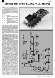
CIRCUIT DESCRIPTION<br />
All connection between the inputs at<br />
the left and the outputs at the right of<br />
the circuit diagram in Figure 6 are<br />
interconnected by screened cable. The<br />
screen of this cable is earthed.<br />
Diode D 2 is arranged to make it<br />
light when data are being sent to IC 2 .<br />
Controller IC 1 provides the requisite<br />
control signals, for which purpose I/O<br />
pins PA 0 , PA 1 , and PA 2 are the DATA,<br />
CLK and WRITE-LOAD outputs<br />
respectively. The 16 I/O pins at the left<br />
of the IC function as analogue inputs.<br />
D5 D4 D3 D2 D1 D0<br />
Figure 4. Timing diagram<br />
of the three-wire<br />
mode of operation.<br />
Figure 5. Clarification<br />
of how two 8-bit bytes<br />
are constructed.<br />
0<br />
0<br />
0<br />
.<br />
.<br />
.<br />
.<br />
.<br />
1<br />
1<br />
1<br />
970037 - 15<br />
These pins are sampled<br />
in turn; the input data<br />
so found is converted<br />
into a control signal for IC 2 .<br />
It will be seen that the inputs into<br />
IC 1 are all direct voltages. The attenuation<br />
level as well as the left/right<br />
information for each channel is set<br />
with the aid of potential dividers. The<br />
wipers of the slide potentiometers<br />
with which the attenuation of the<br />
input signals is set are linked to ‘P1’,<br />
‘P2’, and so on, respectively. The other<br />
terminals of the potentiometers are<br />
connected to +5 V and 0 respectively.<br />
When the potentiometers are almost<br />
closed, the voltage is low and the<br />
attenuation great. When they are gradually<br />
opened, the potential at their<br />
wiper rises and the attenuation is<br />
reduced.<br />
A potential divider<br />
consisting of three<br />
DATA ATTENUATION<br />
38 Elektor Electronics 3/97<br />
0<br />
0<br />
0<br />
.<br />
.<br />
.<br />
.<br />
.<br />
1<br />
1<br />
1<br />
0<br />
0<br />
0<br />
.<br />
.<br />
.<br />
.<br />
.<br />
1<br />
1<br />
1<br />
0<br />
0<br />
1<br />
.<br />
.<br />
.<br />
.<br />
.<br />
0<br />
1<br />
1<br />
0<br />
1<br />
0<br />
.<br />
.<br />
.<br />
.<br />
.<br />
1<br />
0<br />
1<br />
0dB<br />
-1dB<br />
-2dB<br />
.<br />
.<br />
.<br />
.<br />
.<br />
-61dB<br />
-62dB<br />
-63dB<br />
970037 - 16
2<br />
L<br />
R<br />
LEVEL<br />
P2<br />
S3<br />
S4<br />
P4<br />
S7<br />
S8<br />
resistors is provided for<br />
the left/right information<br />
for each channel.<br />
The individual resistors<br />
are switched with the<br />
aid of two switches. For<br />
R5<br />
10k<br />
5V<br />
Elektor Electronics 3/97<br />
47k<br />
82k<br />
47k<br />
R13<br />
10k<br />
5V<br />
47k<br />
82k<br />
47k<br />
5V +5V 5V<br />
P5<br />
S9<br />
S10<br />
R17<br />
10k<br />
5V<br />
47k<br />
82k<br />
47k<br />
R6<br />
R7<br />
R8<br />
C2<br />
330n<br />
C4<br />
R14 330n<br />
R15<br />
R16<br />
C5<br />
R18 330n<br />
R19<br />
R20<br />
C7<br />
R26 330n<br />
P1<br />
S1<br />
S2<br />
P7<br />
R25<br />
10k<br />
P8<br />
S13<br />
S14<br />
5V<br />
47k<br />
82k<br />
47k<br />
R27<br />
R28<br />
P3<br />
S5<br />
S6<br />
P6<br />
S11<br />
S12<br />
S15<br />
S16<br />
R1<br />
10k<br />
5V<br />
47k<br />
82k<br />
47k<br />
R9<br />
10k<br />
5V<br />
47k<br />
82k<br />
47k<br />
R21<br />
10k<br />
5V<br />
47k<br />
82k<br />
47k<br />
R29<br />
10k<br />
5V<br />
47k<br />
82k<br />
47k<br />
R2<br />
R3<br />
R4<br />
C1<br />
330n<br />
C3<br />
R10 330n<br />
R11<br />
R12<br />
C6<br />
R22 330n<br />
R23<br />
R24<br />
C8<br />
R30 330n<br />
R31<br />
R32<br />
Figure 6. Circuit diagram<br />
of the <strong>mixer</strong> <strong>board</strong>. The<br />
dashed lines near Channel<br />
2 indicate how the<br />
potentiometer and<br />
switches for the left-hand<br />
and right-hand channels<br />
must be connected.<br />
C16<br />
100n<br />
C9<br />
22p<br />
C17<br />
10µ<br />
63V<br />
1<br />
2<br />
3<br />
4<br />
5<br />
6<br />
7<br />
8<br />
3 X1<br />
8MHz<br />
C10<br />
22p<br />
S17<br />
MUTE<br />
instance, in the<br />
case of channel 2, it<br />
is easily calculated<br />
that when both<br />
switches are open,<br />
the voltage at the<br />
10k<br />
R36<br />
23<br />
PA4<br />
TIMER<br />
2<br />
6<br />
22<br />
PC7<br />
PA5<br />
NMI<br />
5<br />
7<br />
PC6<br />
21<br />
PA6<br />
PA0<br />
27<br />
8<br />
PC5 IC1 PA1<br />
26<br />
20<br />
PA7<br />
PA2<br />
25<br />
9<br />
PC4<br />
PA3<br />
24<br />
19<br />
PB0 ST62T25<br />
12<br />
PB7<br />
18<br />
PB1<br />
13<br />
PB6<br />
17<br />
PB2<br />
RESET<br />
11<br />
14<br />
PB5<br />
16<br />
PB3<br />
15<br />
PB4<br />
OSC<br />
IN OUT<br />
VPP 10<br />
DGND 1<br />
VSS<br />
2<br />
1<br />
4<br />
5V<br />
28<br />
D2<br />
DATA<br />
5V<br />
10k<br />
680Ω<br />
R33<br />
C11<br />
22µ<br />
40V<br />
R34<br />
100n<br />
28 SYSTEM MUTE<br />
27 DATA IN<br />
DATA OUT 3<br />
26 CLK<br />
VDD<br />
4<br />
25 WRITE<br />
VIN1<br />
5<br />
NC (SHIELD) 6<br />
SSM2163<br />
24 LD<br />
23 NC (SHIELD)<br />
VIN3<br />
7<br />
NC (SHIELD) 8<br />
TOP VIEW<br />
22 VIN2<br />
21 NC (SHIELD)<br />
VIN5<br />
9<br />
20 VIN4<br />
VCC<br />
10<br />
19 NC (SHIELD)<br />
VIN7<br />
11<br />
18 VIN6<br />
VEE<br />
12<br />
17 AGND<br />
ACOM 13<br />
16 VIN8<br />
VOUTL<br />
14 15 VOUTR<br />
C14<br />
junction of R 7 and R 8 is about 1.3 V.<br />
The input signal is then not transferred<br />
to the output of the <strong>mixer</strong><br />
<strong>board</strong>. When S 3 is closed and S 4 is<br />
open, the potential at junction R 7 -R 8 is<br />
about 1.8 V and the input signal is<br />
39<br />
100n<br />
C15<br />
C12<br />
10µ<br />
63V<br />
28 VDD VCC<br />
SYSTEM MUTE<br />
5<br />
VIN1<br />
ACOM<br />
13<br />
22<br />
VIN2 IC2<br />
7<br />
VIN3 VOUTL<br />
14<br />
20<br />
9<br />
VIN4<br />
VIN5<br />
DATA OUT<br />
3<br />
18<br />
11<br />
16<br />
VIN6 VOUTR<br />
VIN7<br />
SSM2163<br />
VIN8<br />
SHIELD<br />
15<br />
6<br />
27<br />
26<br />
25<br />
24<br />
DATA IN<br />
CLK<br />
WRITE<br />
LD<br />
SHIELD<br />
SHIELD<br />
SHIELD<br />
SHIELD<br />
8<br />
19<br />
21<br />
23<br />
C13<br />
10µ 63V<br />
4<br />
10<br />
1<br />
DGND AGND<br />
17<br />
VSS VEE<br />
5V<br />
5V<br />
JP1<br />
2<br />
D<br />
C<br />
W<br />
820Ω<br />
12<br />
R35<br />
D1<br />
5V<br />
5V<br />
+5V<br />
POWER<br />
0<br />
<strong>–</strong> 5V<br />
970037 - 11<br />
5V<br />
5V<br />
L<br />
R<br />
Anzeige
microcontroller control<br />
The microcontroller used in the <strong>mixer</strong> <strong>board</strong> is a Type ST62T25 from SGS-<br />
Thomson. This device has 20 I/O lines which can be switched at will when<br />
the program is running to form an input or output in various configurations.<br />
Sixteen of them may be linked to the internal analogue-to-digital converter<br />
(ADC) to form the lines via which the positions of the slide potentiometers and<br />
the switches are written.<br />
The positions of the slide potentiometers and the switches are continuously<br />
sampled by the software, which also processes the results of the analogueto-digital<br />
conversions and stores them in the internal RAM. When even one of<br />
these settings differs from the previous one, the microcontroller passes all<br />
data to the <strong>mixer</strong> IC.<br />
The allocation of the port lines to potentiometers and switches looks rather<br />
untidy on the circuit diagram; this results from the requirement of making the<br />
layout of the printed-circuit <strong>board</strong> as straightforward as possible. <strong>No</strong>te that<br />
PA 0 <strong>–</strong>PA 3 cannot be linked to the ADC.<br />
n<br />
initialization<br />
scanning<br />
potentiometers<br />
settings<br />
altered<br />
?<br />
y<br />
send to<br />
<strong>mixer</strong> <strong>board</strong><br />
970037 - 17<br />
applied to the left-hand channel.<br />
When S 4 is closed and S 3 open, the<br />
potential at junction R 7 -R 8 is about 2.5<br />
V and the input signal is applied to the<br />
right-hand channel. When both<br />
switches are closed, the potential<br />
across R 8 is 5 V and the input signal is<br />
applied to both outputs (mono).<br />
To carry out these tasks, a special<br />
program is loaded in the ST62T25. The<br />
manner in which this device converts<br />
the direct voltages at the inputs into a<br />
Elektor Electronics 3/97<br />
Analogue-to-digital<br />
The simplest way of operating the ADC of<br />
the ST62 controllers is starting the conversion<br />
and waiting in a loop until the EOC<br />
(end-of-conversion) bit goes high, whereupon<br />
the normal process of the program<br />
can be continued. From a software point<br />
of view, this may be all right, but it appears<br />
that owing to internal and external noise it<br />
is impossible to obtain an accuracy of even<br />
6 bits. The use of a WAIT command, which<br />
disables a large part of the processor,<br />
brings about a real improvement. The ADC<br />
generates an interrupt when the EOC goes<br />
high and this re-enables the processor.<br />
The SSM2123 uses only six bits to set the<br />
attenuators and there is therefore nothing<br />
against ignoring the two LSBs of the ADC.<br />
Yet, this is not sufficient to achieve a stable<br />
setting of the <strong>mixer</strong> IC over the whole<br />
control range of the potentiometers: in<br />
some situations D 2 flashes to indicate that new data are being transferred.<br />
This is, of course, self-evident, because even if the two LSBs are ignored they<br />
continue to exert some influence. If bit 1 is high, a variation of just one LSB<br />
is sufficient to affect higher, relevant bits.<br />
There are ways and means of solving this. For instance, it would be possible<br />
to sample a potentiometer a couple of times in succession and average the<br />
results. In the present design, a simple means is used: the entire 8-bit ADC value<br />
is retained, while the next sample is accepted only if its value differs by <strong>more</strong><br />
than two LSBs from the previous one. This matter is less problematical when<br />
the state of the switches is written: in that case only four results are possible:<br />
some noise and a slight accuracy in the potential divider do not matter much<br />
Digital to the <strong>mixer</strong> IC<br />
Sending data to the SSM2163 is fairly straightforward. Three lines from port<br />
A of the ST6225 carry the CLK, WRITE and data signals. Unfortunately, with<br />
this configuration of the port, this cannot be effected with direct setting and<br />
resetting of the port bits. Because of space considerations, this cannot be further<br />
explained here.<br />
control signal for IC 2 is described in<br />
the box on p. xx.<br />
Circuit IC 1 is supplied by an asymmetrical<br />
voltage of 5 V, and IC 2 by a<br />
symmetrical line of ±5 V. Diode D 1<br />
functions as on/off indicator. Jump lead<br />
JP 1 enables the screen of the cables to<br />
be linked to the negative supply line.<br />
This may be useful if hum occurs,<br />
unlikely though that may be. [970037]<br />
(to be continued)<br />
In passing …<br />
Sitting in a small restaurant the<br />
other day, I was intrigued to overhear<br />
a conversation between a small<br />
group of people at the next table<br />
about the relative merits or otherwise<br />
of digital cameras (apparently<br />
one of them had been given one as<br />
a Christmas present). It was argued<br />
that pictures from a digital camera<br />
are nowhere near as good as those<br />
from a ‘real’ camera. In a sense, this<br />
is true, of course, because a goodquality<br />
colour transparency requires<br />
about 80 million pixels (the tiny<br />
individual spots that all pictures are<br />
made up of), whereas a digital camera<br />
manages not much <strong>more</strong> than a<br />
few hundred thousand pixels (since<br />
its CCD <strong>–</strong> charge-coupled device <strong>–</strong><br />
contains only that number of<br />
diodes). A simple 8-bit image allows<br />
each pixel to have 256 possible<br />
shades of grey or basic colours.<br />
With 24-bit colour (which most<br />
graphics programs use) each pixel<br />
can have <strong>more</strong> than 15 million different<br />
colour possibilities. <strong>No</strong>w, the<br />
memory in a digital camera just cannot<br />
cope with this: even a dozen 24bit<br />
colour snapshots, each made up<br />
of only 200,000 pixels, will occupy<br />
7.2 MB of memory (may be compressed<br />
by, for instance, JPEG to<br />
about 2 MB). A picture of the quality<br />
needed by a magazine such as<br />
ours would take up 60-80 MB. How<strong>ever</strong>,<br />
in publishing, a dark-room is a<br />
thing of the past. Colour-negative<br />
and transparency film is now normally<br />
machine-processed and<br />
scanned directly into digital files.<br />
The pictures are then edited on a<br />
computer screen and inserted<br />
directly into the electronic page<br />
make-up. Consequently, many professional<br />
photographers are already<br />
using digital cameras for situations<br />
where speed is important.<br />
It is fairly certain that in the not too<br />
distant future there will be <strong>more</strong> digital<br />
cameras around than optical<br />
ones, in spite of the former’s current<br />
imperfections. After all, the average<br />
person will only want to take snapshots,<br />
not become a photographic<br />
artist. If you are not convinced of<br />
this, look at the number of camcorders<br />
around which operate on<br />
the same principle as the digital still<br />
camera.<br />
41<br />
LS/975024