


Director of Process Engineering and Metallurgy
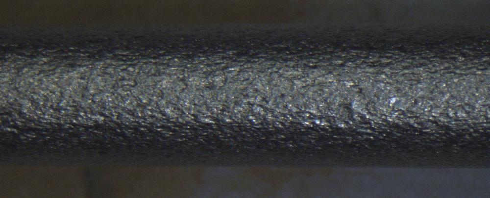
Poor grain size control can cause surface defects from slight to severe. This orange peel appearance on the surface of this tube is a byproduct of poor microstructure and severe tensile loading.
You fabricate corrosion-resistant tube all day long, making bends and end forms in varying severity, and usually all goes well. However, you notice exceptions. Once in a while, a tube splits during bending. Occasionally you receive a shipment of tube that has a poor surface finish, an orange-peel appearance. From one lot to the next, the dimensions are within the specified tolerances, and chemistry is always within acceptable limits, so what’s the problem?
The defects could be the result of improper grain size.
Suppliers that draw or reduce tube to the required characteristics use a complex series of cold working and annealing steps to impart the characteristics the tube needs—surface finish, strength, dimensions, and grain size. Each alloy, and sometimes each heat lot, has its own nuances. To achieve a balance between the grain size and mechanical properties, proper process planning is critical. Ultimately, the time and effort pays for itself in successful manufacturing and timely delivery.
Grain size is a key measure that defines the characteristics of metals and alloys. However, this factor rarely gets the attention it warrants. Generally, metals are selected for an application based on their mechanical strength, suitability for fabrication, corrosion resistance, pressure resistance, and a host of related characteristics. While designers responsible for material selection have various data compilations to help them choose the right material for the application, grain size rarely is a top priority for data compilation.
For a number of products such as heavy-wall pipes, grain size does not matter. However, as the walls get thinner, grain size plays an increasingly important role. In comparing two tubes of identical dimensions and wall thickness, the one with the finer grains has more grains; more grains contribute to the tube’s ability to withstand internal pressures or external forces. In other words, when all other factors are held constant, a finer grain makes a stronger metal.
Grain size is measured in transverse and longitudinal sections. The common industry standards are ASTM E112 and ISO 643:2012. The basic practice involves mounting and polishing sections and then etching with a suitable acid, sometimes aided by a small amount of electrical current. The metallographer evaluates the resulting microstructure by magnifying it 100 times (see Figure 1). The relevant standard provides guidance in assigning the grain size number. Automated grain size measurement has become common, thus removing any guesswork from the process. However, for some alloys, because of their inherent structure of a mixture of small and large grains, automation is difficult to implement. Nevertheless, with properly documented procedures for evaluation, automated measurement is a viable practice.
It is important to note that grain size numbers work inversely to the actual size. That is, as the grains increase in size, the grain size numbers decrease (see Figure 2).
Grain size usually is specified by a product engineer and is based on the application and wall thickness. For walls 0.050 inch and thicker, grain size 5 usually is acceptable; for wall size around 0.015 in., grain size 6 usually is acceptable. For even smaller wall sizes, around 0.005 in., a grain size of 7 or finer is required. In general, as the wall thickness gets lighter, the need for a finer grain size increases. For special applications like electropolishing, even finer grain sizes are specified (sometimes ASTM number 8 or finer) because a finer grain size contributes to a smooth surface.
Many factors influence the grain size. These include the alloy chemistry, the cold work done to the material, and the annealing process.
Alloy Chemistry. Certain elements, such as titanium and niobium, inhibit grain growth in stainless steels. For some stainless steels, a lower carbon content does the opposite, contributing to grain growth.
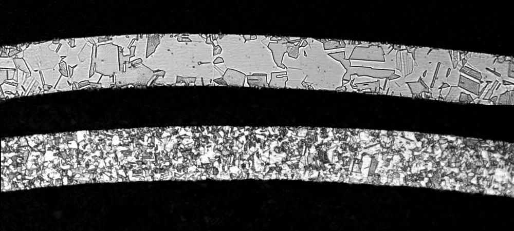
Figure 1
The uncontrolled grain size in a stainless steel alloy tube, wall thickness 0.005 (top), will cause trouble if the tube is subjected to severe forming stresses. Small grains contribute to the material’s ability to withstand severe stresses.
Amount of Cold Work. The higher the severity of cold work, the more time is taken to dissolve the grains into the solution and the less time is available for grain growth. The net result is finer grains.
Type of Cold Work. Cold work is achieved by either tensile force (draw bench operations) or compressive force (pilger mill operations). Typically a higher amount of cold work can be achieved in compressive reduction than drawing, making it easier to achieve finer grains, holding constant all other factors (chemistry, annealing temperature, and dwell time). Conversely, using the same material temperature on material subjected to a smaller amount of cold work will result in a larger grain size, holding other variables the same.
Annealing Temperature and Time. The higher the annealing temperature, the faster the process of dissolving the cold-worked, elongated grains into solution and consequent grain growth. This holds true for the dwell time also; a longer time at the target temperature promotes grain growth.
Anneal Cooling Rate. A faster cooling rate enables the completion of the recrystallization process in the shortest possible time, reducing the tendency for grains to grow. In addition to preventing carbide precipitation in the grain boundaries, a faster cooling rate reduces the time at the target temperature.
Cold drawing mills generally receive material in an average grain size of 3.5 to 6, depending on the alloy. These materials have to be processed to achieve a grain size of 5 to 8, depending on the client’s requirements. Economic process design requires using a minimum number of cold work and anneal cycles to reach a final size and meet the finished product specifications. Some of these requirements actually work against each other, making it extremely challenging to control them. Because the alloy choice has been made at this point, it’s not a factor. Therefore, the two key considerations in the process design are the amount of cold work and the annealing cycle (temperature and time at temperature).
Higher annealing temperatures and longer soak times generate a softer material, which can withstand more severe cold work in the next step. These factors also promote grain growth, which eventually can become an insurmountable problem if the wall isn’t very thick. If this practice continues, the grain size reaches a point of no return, making it impossible to recover and achieve the desired grain size.
Now consider the mechanical property requirements. If the annealing temperature and dwell time decrease continuously, the material’s strength increases over each successive cycle. Without proper checks and balances, the product has the potential to fail because it becomes increasingly brittle.
Tube manufacturers should give all of these factors due consideration when developing a process, weighing each step’s contributions to the process against its efficiency. It’s also important to validate a process before initiating full-scale production. Using ISO guidelines, a three-lot validation is acceptable.
Cold working makes alloys stronger and harder while reducing the material’s ductility; annealing reduces strength and hardness while restoring ductility. The sequence of change in microstructure and mechanical properties comprises three steps: Cold work, heating the material to its recrystallization temperature, and soak time at the elevated temperature (see Figure 3).
The simplest way to achieve and maintain small grain size is to use lower annealing temperatures while keeping it within the range allowed for the alloy. This is assuming that the extent of cold work has remained unchanged. The result is that the yield strength and the ultimate tensile strength decrease, and ductility is restored, as indicated in the center of Figure 2. The tradeoff is that the material retains some of its strength and hardness, making it more difficult to cold work in the next cycle. For stainless steels, this effect is not as prominent as in some of the high strength INCONEL® alloys.
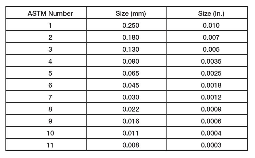
Figure 2
A metal grain’s physical size and its grain number are inverse of each other.
Proper process development requires a balanced approach. The annealing temperature must be dropped at each cold work and anneal cycle, but not by a drastic amount. This is associated with a slight drop in the percentage of cold work where required, which prevents unacceptable consequences at draw benches, such as breaking tags, heavy chatter, scratches, or gouges that develop during drawing. For high-strength alloys, balancing the cold work against a lower annealing temperature can make the difference between success and failure.
A three-cycle control step is common, although a bigger difference between the initial and final grain size can lead to a four- or five-step control process.
For stainless steels the initial annealing temperature may be about 1,950 degrees F, but toward the end of the process, a lower temperature, perhaps 1,850 degrees F, might be necessary to achieve the desired grain size. The adverse effect on mechanical properties is not so severe for most stainless steels, and often they can be drawn successfully after lower-temperature anneals. However, heats that are known to have higher strength levels—whether based on experience with the alloy or the material certification—require precautionary steps.
Some of the INCONEL alloys with high strength levels necessitate an alternate approach. To control the grain size properly these alloys are annealed at incrementally lower temperatures over consecutive cold work and anneal cycles. The smaller drop in annealing temperature at each cycle minimizes the adverse impact on mechanical strength and hardness and thereby intermediate cold working capability. At the last anneal a higher temperature is used, sacrificing a little bit of the grain size but significantly improving the ductility of the end product. The technique is well established but needs strict in process control.
A nondestructive test (NDT) is necessary for many specialized tubing applications—nearly all aerospace and nuclear tubing and quite a bit of the product used in the medical field. Ultrasonic testing is one of the most commonly used method for evaluating tubing used in these critical applications.
Control of grain size is the key to a successful ultrasonic test. An average grain size of 6 or finer is required for most stainless alloys. For light walls, around 0.015 in. thick, grain size 7 or finer is the target. A mix of large and small grains poses problems by creating noise. Such noise makes detecting small defects difficult because often they are hidden by the noise. A mix of sizes makes a reliable test nearly impossible.
For INCONEL alloys in medium to heavy wall thicknesses, an average grain size of 5 or finer is acceptable. Some of these alloys have an inherent mixed-grain structure, and control of the large grains requires close attention. The noise pattern is similar to that described in the previous paragraph. Achieving a reliable test result requires an NDT standard with noise level comparable to that of the tubes under test.
Fabricators typically do not specify the intended use of the tubing, and few ask for a specific grain size. Tubing manufacturers usually make products that conform to a specific industry standard, and these generally don’t specify a grain size. When a fabricator procures a light-wall tube made to an industry standard and the tube works for the application, all is well, but future orders might not deliver the same performance.
When conditions allow, fabricators should share information with their suppliers about the intended use of any light-wall tube, such as the type and severity of bending, the extent of flaring, maximum flange diameter, and machining processes. This provides the tubing manufacturer the opportunity to optimize the process design before beginning full-scale production. If the lot of tubing performs well for the fabricator, the fabricator should provide this feedback to the supplier. This helps to lock down the process steps and process controls to ensure a steady supply of reliable tubing for the intended application.
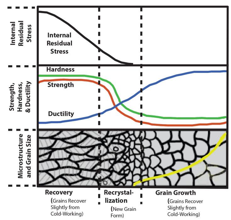
Figure 3
A heavily cold-worked structure has elongated grains and a large amount of residual stress (left). A moderate amount of annealing causes the elongated grains to recover and new grains to form (center). Extended annealing is associated with grain growth (right).


The Tube and Pipe Journal became the first magazine dedicated to serving the metal tube and pipe industry in 1990. Today, it remains the only North American publication devoted to this industry, and it has become the most trusted source of information for tube and pipe professionals.
start your free subscription
Easily access valuable industry resources now with full access to the digital edition of The Fabricator.

Easily access valuable industry resources now with full access to the digital edition of The Welder.

Easily access valuable industry resources now with full access to the digital edition of The Tube and Pipe Journal.

Easily access valuable industry resources now with full access to the digital edition of The Fabricator en Español.
In this episode of The Fabricator Podcast, Caleb Chamberlain, co-founder and CEO of OSH Cut, discusses his company’s...


