IRON-CARBON PHASE DIAGRAM (PT1) How to build the phase diagram
Matteo Sporchia
Sales Export Manager on Steel products | Refractory and Graphite Electrodes Technical Expert | Founder of #products4steelmaking
1. INTRODUCTION
In this article we're going to explain how to build the iron - carbon phase diagram.
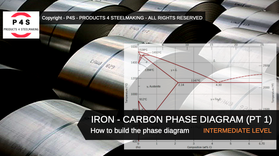
The Fe - C diagram (also called the iron - carbon phase or equilibrium diagram) is a graphic representation of the respective microstructure states of the alloy iron - carbon (Fe-C) depending on temperature and carbon content.
To explain this diagram, an introduction about metal structures and pure iron must be done.
2. UNIT CELL CUBIC STRUCTURES
Before to explain the Fe-C diagram we've to introduce the two structures that are involved in the diagram and precisely:
- BODY-CENTERED CUBIC (BCC) structure, in which there's an atom at each corner of the cube and one in the center;
- FACE-CENTERED CUBIC (FCC) structure, in which there's an atom at the corner of each unit cell and one in the center of each face, but there's no atom at the center of the cube;
Here below we can see the main differences between the two structures and relevant properties:

3. IRON
Iron (Fe) is an allotropic metal that change behavior based on temperature. It's a relatively soft and ductile metal. It exists in more than one type of lattice structure (BCC/FCC). In fact there're four allotropic transformations and five phases that iron can assume. All of these can be easily represented using a COOLING CURVE where the following phases can be identified:
- LIQUID PHASE (L), above 1539 °C iron is in the liquid phase;
- DELTA FERRITE (δ-Fe), if we slowly cooling down the pure iron below his melting point (1539 °C) it will crystallize into a phase, which has a body-centered cubic (BCC) structure;
- GAMMA FERRITE (γ-Fe), cooling down further until 1400 °C, iron assume a new phase called gamma (austenite), which has a face-centered cubic (FCC) structure;
- ALFA FERRITE non magnetic (α-Fe), at 910 C an below the iron assume a new structure called alfa ferrite, which is again a BCC structure;
- ALFA FERRITE magnetic (α-Fe), under 770 C, iron assume a magnetic properties maintaining the BCC structure of alfa ferrite;

4. Fe-C PHASE DIAGRAM
As mentioned before the Fe-C phase diagram is the representation of all the phases and structures of the alloy iron - carbon based on the different temperature and carbon content.
This diagram is particular important in order to:
- Classify the alloy into different groups like steel and cast iron;
- Identify the different phases of iron;
- Identify the microstructure of the different phases;
- Provide the information regarding solidification and heat treatments;
We're going to see how build the diagram step by step starting to the essential temperatures indicated regarding the pure iron.
Temperature (°C) is indicated in the y-axis and weight carbon content (wt % C) is indicated in the x-axis. In the diagram is represented a maximum value of 6.67% C as there's no particular application in engineering for carbon content above this value.

Now we've to introduce the three invariant and isothermal reactions as indicated here below:
- PERITECTIC REACTION, the liquid (at 0.5% C) and δ-Fe (at 0.1% C) phases transform into a austenite (with 0.2% C) at temperature of 1493 °C;
- EUTECTIC REACTION, the liquid solidifies as a phase mixture of austenite (with 2.1% C) and cementite (with 6.67% C) at temperature of 1147 °C;
- EUTECTOID REACTION, austenite (at 0.8% C) transforms into a phase mixture of ferrite (with 0.02% C) and cementite (with 6.67% C) at temperature of 727 °C;

The three invariant reactions can be easily represented in the diagram as three horizontal lines with fixed temperature as indicated here below:

Now we can identify all the phases of the diagrams which are:
- LIQUID PHASE (L)
- DELTA FERRITE PHASE (δ-Fe), is an interstitial solid solution of C in δ-Fe (BCC) in the high temperature region of the diagram. It's stable at temperature above 1400 °C and melts at temperature above 1539 °C;
- GAMMA FERRITE PHASE (γ-Fe), is an interstitial solid solution of C in γ-Fe (FCC). It's also called austenite. Is not stable below 910 °C. The max solubility of C is about 2.1% at 1147 °C. It's has high formability;
- ALFA FERRITE PHASE (α-Fe), is an interstitial solid solution of C in α-Fe (BCC). It's a stable form of iron at room temperature. The max solubility of C is about 0.02% at 727 °C. It's a fairly and ductile phase, actually the softest one structure of the diagram;
- CEMENTITE (Fe3C), also called as iron carbide. It's an inter metallic compound of iron and carbon with orthorhombic crystal system. It's very hard and brittle phase, actually the hardest structure of the entire diagram;

5. PROPERTIES OF THE DIFFERENT PHASES
Based on the microstructures each phase has different properties as indicated here below:

6. GENERAL CLASSIFICATION
Based on the general form of the diagram we can start to classify the alloy Fe-C into these groups:
- IRON, with a carbon content less than 0.008% in α-Fe structure at room temperature;
- STEEL, with a carbon content between 0.008 and 2.1% (generally less than 1%) in α-Fe + Fe3C structure at room temperature;
- CAST IRON, with a carbon content between 2.1 and 6.67% (generally less than 4.5%);
In the future articles we are going to talk about the different types of steels and cast irons that can be identified through the diagram.
Author: Eng. Matteo Sporchia
Copyright - P4S - Products 4 Steelmaking - ALL RIGHTS RESERVED
TAKE A LOOK ABOUT THE OTHER OUR ARTICLES ...
Kindly click on the article you are interested in:
- OUTLOOK OF GRAPHITE ELECTRODES IN CHINA
- THE FUTURE OF STEEL INDUSTRY
- REFRACTORIES (PART 1) - General Introduction
- ELECTRIC ARC FURNACE AC (PART 1) - Layout & Components
- ELECTRIC STEELMAKING - The Processing Route
- BASIC OXYGEN STEELMAKING - The Processing Route
- GRAPHITE ELECTRODES - Manufacturing Process
HOW TO JOIN P4S LINKEDIN GROUP?
If you're interested to know more about anything related to the iron and steelmaking fields you can easily join our LinkedIn group at this link ---> PRODUCTS 4 STEELMAKING asking to be invited.
PLEASE FOLLOW OUR LINKEDIN HASHTAG
Just click here ---> #products4steelmaking and follow our hashtag.

#products4steelmaking #steel #steelmaking #technology #engineering #metallurgy #iron
Mtech. in Water Engineering and Management , IIT Kharagpur, west Bengal.
1yAll are masters in this field, can any one reply my question. Q. Is heat treatment(SR) is necessary in Explosion bonded Cladded plate.(MOC SS516 GR 70 & Nickel alloy C-22) ?
Mechanical Technician
2ywith reference to the iron-carbon phase equilibrium diagram, explain why the Ar point are likely to be more useful than Ac point when treating steel
Site Director in Tokai COBEX
4yI remember that I had to remember :)
Professional trader and technical analyst - Stock markets (India & USA)
4yNest you should explain Ellingham diagram. which shows relative stability of oxides.
Técnico de Inspeção de Equipamentos
4yNice article,